Topic 13
RADAR (RAdio Detection And Ranging) Imaging is an active remote sensing system which bounces microwave energy from a target and records the energy that returns to the sensor.
Plan Position Indicator (PPI) Radar is a precursor to airborne and satellite imaging systems and is utilized for navigation and target location using a rotating antenna with images produced on a circular view screen. PPI Radar continues to be used for aircraft and ship navigation as well as for weather applications.
Side-Looking Airborne Radar (SLAR) is an early form of imaging radar and was developed for military terrain reconnaissance and surveillance where a strip of the ground parallel to and offset to the side of the aircraft was imaged during flight. In the 1960s imaging radars were declassified and began to be used for civilian mapping applications.
All-weather Operation: the transmitted and reflected microwave energy penetrates through cloud cover, dust, haze, and rain.
Day or Night Operation: Radar sensors can operate both day or night since they do not require an external energy source.
How Radar Imaging Works: Microwave energy pulses (A) are emitted at regular intervals and focused by the antenna into a radar beam (B) directed downwards and to the side. The radar beam illuminates the surface obliquely at a right angle to the motion of the platform. Objects on the ground reflect the microwave energy depending on factors such as roughness and attitude. The antenna receives this reflected (or backscattered) energy (C).
Energy/Time Graph: By measuring the time delay between the transmission of a pulse and the reception of the backscattered "echo" from different targets, their distance from the radar and thus their location can be determined. As the sensor platform moves forward, recording and processing of the backscattered signals builds up a two-dimensional image of the surface.
In airborne and spaceborne radar imaging systems, the platform travels forward in the flight direction (A) with the nadir (B) directly beneath the platform. The microwave beam is transmitted obliquely at right angles to the direction of flight illuminating a swath (C) which is offset from nadir. Range (D) refers to the across-track dimension perpendicular to the flight direction, while azimuth (E) refers to the along-track dimension parallel to the flight direction.
Near Range is the portion of the image swath closest to the nadir
track
Far Range is the portion of the swath farthest from the nadir track.
Depression or Grazing Angle is the angle between the horizontal and a
radar ray path.
Slant Range Distance is the radial line of sight distance between the radar and
each target on the surface.
Ground Range Distance is the true horizontal distance along the ground
corresponding to each point measured in slant range.
Incidence Angle is the angle between the radar beam and ground surface
Look Angle is the angle at which the radar "looks" at the surface, or the
angle between vertical and a ray path
The microwave portion of the Electromagnetic Spectrum (EMS) is quite large, relative to the visible, and there are several wavelength ranges or bands commonly used in radar imaging:
| Wavelength Range | Description |
| Ka, K, and Ku Bands | very short wavelengths used in early airborne radar systems but uncommon today |
| X-band | used extensively on airborne systems for military reconnaissance and terrain mapping. |
| C-band | common on many airborne research systems (CCRS Convair-580 and NASA AirSAR) and spaceborne systems (including ERS-1 and 2 and RADARSAT). |
| S-band | used on board the Russian ALMAZ satellite. |
| L-band | used onboard American SEASAT and Japanese JERS-1 satellites and NASA airborne system. |
| P-band | longest radar wavelengths, used on NASA experimental airborne research system |
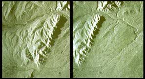
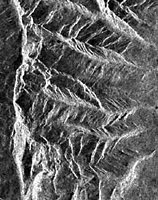
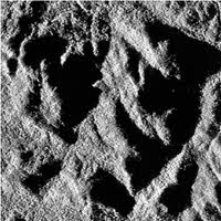
Radar Image Example, Agricultural Fields: These radar images were taken of the same area, but they display significant differences in the way the fileds and crops appear due to the differences in the wavelengths used and the way the radar energy interacts with the target. The L-Band (longer wavelength) provides better resolution than the C-Band.
| C-Band Radar Image | 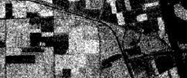 |
| L-Band Radar Image | 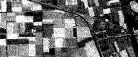 |
Target Interaction and Image Signatures
Unlike aerial photographs and satellite images which are passive remote sensing systems, in active systems such as radar, the brightness or darkness of the image is dependent on the portion of the transmitted energy that is returned back to the radar from targets on the surface. Bright areas are produce by strong radar response and darker areas are from weak radar responses.
The response to radar energy by the target is primarily dependent on three factors:
Surface Roughness: This is the average height variation in the surface cover (measured in the order of centimeters). A surface is considered "smooth" if the height variations are much smaller than the radar wavelength.
Specular Reflection (A) is caused by a smooth surface where the incident energy is reflected and not backscattered.This results in smooth surfaces appearing as darker toned areas on an image.
Diffuse Reflection (B) is caused by a rough surface which scatters the energy equally in all directions. A significant portion of the energy will be backscattered to the radar, such that a rough surface will appear lighter in tone on an image.
Corner Reflection (C) occurs when the target object reflect most of the energy directly back to the antenna resulting in a very bright appearance to the object. This occurs where there are buildings, metallic structures (urban environments) and cliff faces, folded rock (natural environments).
Polarization of the radar signal is the orientation of the the electromagnetic field and is a factor in the way inwhich the radar signal interacts with ground objects and the resulting energy reflected back. Most radar imaging sensors are designed to transmit microwave radiation either horizontally polarized (H) or vertically polarized (V), and receive either the horizontally or vertically polarized backscattered energy.
Polarizing Radar has four possible combinations of both transmit and receive polarizations as follows:
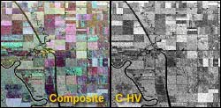
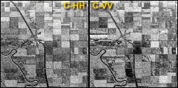
Radar Polarization Example: Agricultural fields were imaged using C-band radar; the bottom two images (C-HH and C-VV) use like polarization and the top right image used cross polarization (C-HV). The upper left image is a combination of the three with each being represented by a color (red,green,blue). The ground targets respond differently to the various combinations of polarized radar. Both wavelength and polarization are important factors in determining image signature.
 |
 |
Radar's spatial resolution or the ability to distinguish between different objects, is dependent on the properties of the microwave radiation and geometric effects. There are two types of spatial or ground resolution: Range Resolution (across-track resolution) and Azimuth Resolution (along-track resolution).
Range Resolution refers to the ability to resolve different objects in the range direction. This requires that the objects be separated by more than half the pulse length. In the diagram objects 1 and 2 cannot be resolved and so will be seen as one object; objects 3 and 4 can be resolved and so will appear as two objects.
Azimuth Resolution refers to the ability to resolve different objects in the azimuth direction or direction of flight. Azimuth resolution is dependent on the angular width (A) of the radiated microwave beam and the slant range distance. The azimuth resolution becomes coarser with increasing distance from the sensor. For example, in the diagram objects 1 and 2 can be resolved, whereas objects 3 and 4 will appear as a single object.
Synthetic Aperture Radar (SAR)
So far we've been discussing radar systems that use a fixed antenna (Real-Aperture Radar - RAR). In order to increase azimuth resolution these systems require an increase in the length of the antenna, but there are physical limitations such as size. In order to over come this limitation, radar systems with a 'synthetic' aperture have been developed which simulate an artificial (or 'virtual') antenna.
In the diagram, target (A) remains in the radar beam for the distance (B) in which the plane travels. The length of the synthesized antenna is equivalent to the distance (B). Synthetic Aperture Radar allows for a resolution of 3 meters from aircraft and 25 meters from satellites.
In radar imaging, distortions of the target image are due to the side-looking viewing geometry and the fact that radar is a distance measuring system. Some of these distortions are scale distortions and relief distortions.
Scale Distortion occurs in the slant-range direction because radar measures distances in the direction of the beam not in ground distance. The same distance on the ground (A1) and (B1) are seen by the radar as (A2) and (B2). The scale is shortened in the near range compared to the far range.
| Slant-Range Scale Distortion | 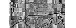 |
| Corrected image | 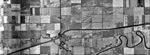 |
Relief Displacement: As in aerial photography radar images are subject to relief displacement but is one-dimensional occurring perpendicular to the flight path. There are two types of relief displacement: foreshortening and layover.
Foreshortening occurs because radar measure distance in the slant-range direction such that the slope A-B appears as compressed in the image (A'B') and slope C-D is severly compressed (C'D')
| Foreshortening | Mountainous Terrain |
 |
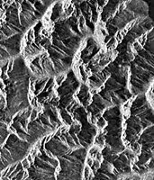 |
Layover occurs when the radar beam reaches the top of a tall feature before it reaches the base. The top of the feature is displaced towards the radar sensor and is displaced from its true ground position - it 'lays over' the base. The visual effect on the image is similar to that of foreshortening.
| Radar Layover | Mountainous Terrain |
 |
 |
Radar Shadow occurs when the radar beam is not able to illuminate the ground surface.
| Radar Shadow | Hilly Terrain |
 |
 |
Airborne versus Spaceborne Radar
The angle at which a radar beam strikes a ground object is an important variable in determining the appearance of an image such as shadow, layover and foreshortening. By altering the incidence angle (higher elevation) it is possible to decrease the image distortions.
| Airborne radar must image over a wide range of incidence angles in order to cover a wide swath. |
Spaceborne radar does not require a wide range of incidence angles to cover a wide swath. |
 |
 |
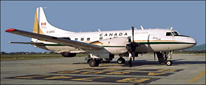
| Canadian Centre for Remote Sensing (CCRS) X-Band and C-Band Synthetic Aperture Radar (SAR) |
|
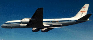
| National Aeronautics & Space Administration (NASA) C-Band, L-Band, and P-Band SAR |
|
| SEASAT (NASA) 1978: First civilian spaceborne SAR |
 |
| ERS-1 (European Space Agency) Launched: 1991 |
 |
| JERS-1 (Japan) Launched: 1992 |
 |
| RADARSAT (Canada) Launch: 1994 |
 |
| SIR-A (Shuttle Imaging Radar) SIR Launch: 1981 |
 |
Stereo Radar: In the same way as airphotos are taken of the ground with forward overlap and side lap in order to view stereo images, a similar application is possible in radar imaging by using different look/incidence angles or opposite look directions.